
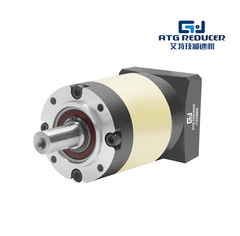
Understanding how to calculate ATG gear reducer output speed is essential for selecting the right gearbox,
matching motor performance, and ensuring stable power transmission in industrial applications. Whether you are working
with conveyors, mixers, packaging machines, automation equipment, or material handling systems, the ability to calculate
gear reducer output speed helps you control torque, optimize efficiency, and avoid system mismatch.
This guide provides a clear, SEO-friendly, and technically useful explanation of ATG gear reducer output speed,
including formulas, calculation examples, influencing factors, advantages, and specification tables. The content is written
in pure English and designed for direct use in blog posts, directory pages, product category pages, and industry knowledge
pages.
An ATG gear reducer is a mechanical transmission device used to reduce input speed and increase output torque.
In industrial motion systems, a gear reducer connects a motor to a driven machine and converts high-speed, low-torque rotation
into low-speed, high-torque rotation. This makes equipment more efficient, more stable, and better matched to the load.
In general, the term ATG gear reducer is often used in the market to describe a gear reduction unit in a
standard industrial drive setup. The exact internal structure may vary, but the working principle remains the same:
the reducer changes the speed ratio between input and output shafts.
Output speed refers to the rotational speed of the reducer’s output shaft after speed reduction. It is usually
measured in revolutions per minute (RPM). If the input motor runs at 1400 RPM and the gear reducer ratio is 10:1, the output
speed is approximately 140 RPM, minus any minor losses from efficiency and slip.
Output speed is one of the most important parameters in gearbox selection because it directly affects:
The most common formula for calculating ATG gear reducer output speed is:
Output Speed (RPM) = Input Speed (RPM) ÷ Gear Ratio
This is the simplest and most widely used calculation method. If the reducer has a gear ratio of 5:1, it means the input shaft
rotates five times for every one rotation of the output shaft. Therefore, the output speed becomes one-fifth of the input speed.
Suppose the motor speed is 1500 RPM and the gear ratio is 15:1.
Output Speed = 1500 ÷ 15 = 100 RPM
In this case, the gear reducer output speed is 100 RPM.
The gear ratio is the core factor in determining output speed. A higher ratio means lower output speed and
higher torque. A lower ratio means higher output speed and lower torque.
| Gear Ratio | Input Speed (RPM) | Approx. Output Speed (RPM) | Typical Result |
|---|---|---|---|
| 5:1 | 1500 | 300 | Higher speed, lower torque gain |
| 10:1 | 1500 | 150 | Balanced reduction |
| 20:1 | 1500 | 75 | Lower speed, higher torque |
| 50:1 | 1500 | 30 | Very low speed, high torque |
If you need an accurate calculation, follow these steps:
A motor runs at 1450 RPM, and the reducer ratio is 12.5:1.
Output Speed = 1450 ÷ 12.5 = 116 RPM
The calculated output speed is 116 RPM.
When output speed decreases, torque increases. This is one of the most important reasons gear reducers are used in industry.
A reducer helps a motor handle heavy loads by converting speed into usable force.
The relationship can be summarized as:
Lower Output Speed = Higher Output Torque
Higher Output Speed = Lower Output Torque
This relationship is valuable in applications where load resistance is high, startup force is important, or process control
requires stable low-speed operation.
Although this article focuses on ATG gear reducer output speed, torque is closely related. A simplified torque
estimation formula is:
Output Torque ≈ Input Torque × Gear Ratio × Efficiency
Efficiency is usually less than 100%, so the actual torque is slightly lower than the theoretical result. Common gearbox
efficiency values vary depending on gear type, lubrication, alignment, and load conditions.
In theory, output speed depends on input speed and gear ratio. In real applications, several additional factors may influence
performance:
Accurate gear reducer output speed calculation helps engineers and buyers choose the right drive solution.
It improves system performance and reduces operational risk.
Different industrial systems may require different calculation methods depending on the available data. Here are the most
common cases.
Output Speed = Input Speed ÷ Gear Ratio
Required Gear Ratio = Input Speed ÷ Desired Output Speed
In some cases, motor speed must first be estimated from frequency and pole count before calculating the reducer output speed.
This is common in AC motor systems.
Synchronous Speed (RPM) = 120 × Frequency (Hz) ÷ Number of Poles
After estimating motor speed, apply the gear ratio formula.
| Input Speed (RPM) | Gear Ratio | Output Speed (RPM) |
|---|---|---|
| 960 | 8:1 | 120 |
| 960 | 16:1 | 60 |
| 1450 | 10:1 | 145 |
| 1450 | 25:1 | 58 |
| 1800 | 30:1 | 60 |
| 1800 | 60:1 | 30 |
When evaluating an ATG gear reducer, users often compare several technical parameters. The following table shows common
specification items used across the industry.
| Specification Item | Description | Common Range / Notes |
|---|---|---|
| Gear Ratio | Speed reduction relationship between input and output | Common ratios vary widely depending on application |
| Input Speed | Motor or drive shaft speed entering the reducer | Often based on motor RPM |
| Output Speed | Speed of the driven shaft after reduction | Usually expressed in RPM |
| Rated Torque | Maximum continuous torque capacity | Depends on size and design |
| Efficiency | Ratio of output power to input power | Varies by gear type and lubrication |
| Mounting Type | Installation style and mechanical interface | Foot-mounted, flange-mounted, shaft-mounted |
| Housing Material | Body material used for structural support | Often cast iron or aluminum alloy |
| Lubrication | Oil or grease system used for smooth operation | Critical for long service life |
Gear reducers are widely used because they provide practical benefits in industrial machinery. The major advantages include:
The calculation of ATG gear reducer output speed is relevant in many industries and machine types. Common
application areas include:
Selecting the correct output speed depends on the process requirements. The best choice is the one that matches the load,
machine timing, and desired production result.
Consider the following when determining output speed:
Even a simple formula can produce incorrect results if the input data is wrong. Avoid these common mistakes:
Divide the input speed by the gear ratio. This is the most direct and widely used method.
Yes. A higher ratio reduces output speed and increases torque.
Not always. Real-world factors such as load, friction, and motor variation may cause small differences.
Because it determines whether the machine will operate at the correct working speed and torque level.
In some systems, output speed can be adjusted by changing the motor speed, drive settings, or transmission configuration.
Knowing how to calculate ATG gear reducer output speed is essential for industrial drive design,
equipment matching, and reliable machine operation. The key formula is simple:
Output Speed = Input Speed ÷ Gear Ratio
By understanding gear ratio, torque relationship, efficiency, and application requirements, you can select and apply a
gear reducer more effectively. Accurate output speed calculation supports better performance, reduced wear, improved safety,
and stronger overall system efficiency.
If you are building a blog page, category page, or industry guide, this content can be inserted directly into the middle of
an HTML page and expanded with internal links, product filters, or technical comparison sections for additional SEO value.
This website uses cookies to ensure you get the best experience on our website.

 Chinese
 Español
 Pусский
 Deutsch
 Tiếng Việt


 Phone
Phone
Comment
(0)